|
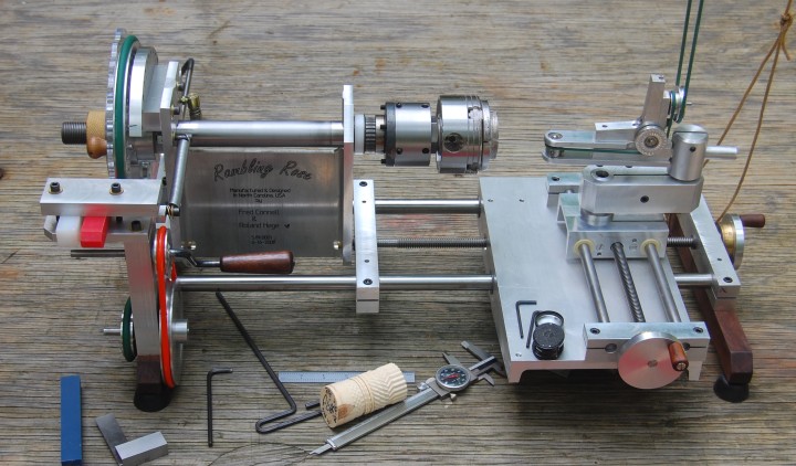
After Roland Hege and I demonstrated our shop Rose Engines this year for our wood turning club and we decided we wanted a Rose Engine that would be mobile enough to easily move around for Rose Engine demonstrations yet stiff enough to produce good work. After much brainstorming we developed the following design criteria for our Rambling Rose Engine. We fabricated and constructed it ourselves in June and July 2008. The drawings are available as PDF files for non commercial personal use only.
Rambling Rose Engine Design Criteria:
- Weight - Mobile weight less than 50 pounds including chuck, tool post and cutting frame. (It will fit in a 32"L x19"W x13"H box)
- Spider - integral fine axial and radial adjusting spider for the chuck with 1" x 8 threads per inch, MT-2 taper & draw bar
- X-Z Compound - integral X-Z axis compound w/ 0.001" calibrated index-able dials. Positive adjustable stops for ornamental work. We plan to incorporate rotation of the X-Z compound to allow cuts along a taper.
- Rubber - front and rear rubber positions
- Speed - 9 to 1 cranking ratio for slow speed control.
- Phase - Ability to phase the rosette cams to the spindle (work piece) to 1/3, 1/4 or 1/8 cam lobe phases. Soon - very fine, repeatable phase adjustment between the rosette cam and the spindle (work piece).
- Multiple cams - change cams quickly and easily and utilize up to 3 rosette cams at one time with independent indexing or phasing to each other and the work piece
- Vibration - Rose Engine rocking motion with headstock and tool post vibration dampening
- Capacity - Work capacity 10" diameter and 7.5" length.
- Tool post - can be repositioned in 3.5" radius from any X-Z position and raised 1" or lowered 0.5 from spindle center. 5/8" round and 9/16" square tool holding capacity.
- Ornamental - Can lock spindle with vernier holes in 1 degree or 360 positions for ornamental decoration work. Soon - very fine repeatable adjustment between the index wheel and the spindle (work piece).
- Threading - We plan to incorporate internal and external thread cutting capacity w/ standard 10 tpi w/ others optional.
Building the Rambling Rose Engine design for your Shop
For use in your shop, you are not so interested in light weight as we are so the first design criteria will be eliminated. We suggest the following changes to the design to make the machine more rigid for bigger profile drilling cutters. We have included the drawing for the steel tube headstock as headstock3.pdf.
- We would make the headstock from a piece of 1/2"x4"x8" steel rectangular tube similar to this drawing.
- The main (X-axis) bars should be larger. 1" to 1.5" diameter would be best. Here is one place where more robust definitely would be better.
- We would increase the length of the X-axis way bars by maybe 3 or 4 inches. But, only if the X-axis bars are made larger as above.
- The Z-axis table could be as much as 6" wide so the way bars could be separated more and made from thicker material with maybe 1/2" thick top.
- The Z-axis bars could be increased 3 or 4 inches in length and increased to 3/4 or 1 inch in diameter for more rigidity.
- The headstock and rubber assembly could be made 1" or 2" taller to handle larger diameter work over the compound.
-
The headstock, rubber assembly and X-Z compound could be attached to a traditional steel/wood table.
We would not perform these changes on our Rambling Rose Engine as our design works perfectly for demonstration work. We get excellent cuts.
Enjoy......Fred Connell & Roland Hege
|