1st & 2nd Generation
Rose Engine

-Fabrication notes 1/27/10
   Prototype:
- Prototype Rose Engine
- Rubber & rosette cam
   Construction:
- Turning the index wheel
- Drilling the index wheel
- Cutting a Rosette cam
- Fabricating T-nut
- Rubber assembly
- Spindle & bearings
- Pivot axle & bearings
- Spindle & frame
- Index wheel installed
- Rocking stop arm
- Rose Engine ready to test
- Chuck holding work
- Turn aluminum on wood lathe
- Hand crank and handle
- Threading follower
- Copy a cam
- Drilling a cam
- Finished rosette cam
- Router assembly
- Boring bar cutters
- Chuck adjusting Spider
- Overhead drive
- Cutting frame
- Rose Engine with router
- Overhead crane
- Drilling frame
- Collet Chuck
- Hardinge compound 9/5/11
- X-Z compound ways 12/28/11
- Test results - Gallery
   Notes:
- Description of a Rose Engine
       by Jon Magill
   Other Stuff:
- Rose Engine 3rd generation mobile
- Wood Lathe works
- Shop jigs homemade
- Downloads & plans

OrnamentalRoseEngine.com E-mail:
info1@OrnamentalRoseEngine.com

Machine assembled for testing -rose2.jpg 640x311 - 53.8k
Custom Rose Engine & Ornamental Lathe
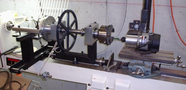
Rose Engine is assembled and ready for a hand driven test.

The Rose Engine is mounted on a Jet cast iron lathe bed.   The bearing blocks have been cut to rough size, drilled for the alignment and mounting holes; and bored for the bearings.   The Rose Engine is assembled for the first hand driven test. A router with a variable speed control is currently being used for the cutter.   The X-Y compound has been turned 90 degrees since this picture and the longer axis was reversed in its ways to locate the handle to the front.   It can now be turned either way if needed.

1x3 bar_rust.gif
Rose Engine Rose Engine barleycorn design barley10.jpg 65x65-2.7k
           OrnamentalRoseEngine.com
E-mail: info1@OrnamentalRoseEngine.com